As with any network, there must be a method to handle collisions. With most modern forms of Ethernet supporting full-duplex, each PHY has full bandwidth all the time to transmit and receive simultaneously. As 10BASE-T1S supports multi-drop, three or more PHYs can be electrically connected to the same physical medium (UTP) in half-duplex mode. As a result, each individual PHY can no longer transmit at any time it wants. There must be a way to enable these PHYs to coordinate when they are allowed and not allowed to transmit. A new method designed for 10BASE-T1S is called Physical Layer Collision Avoidance, or PLCA for short.
PLCA Overview
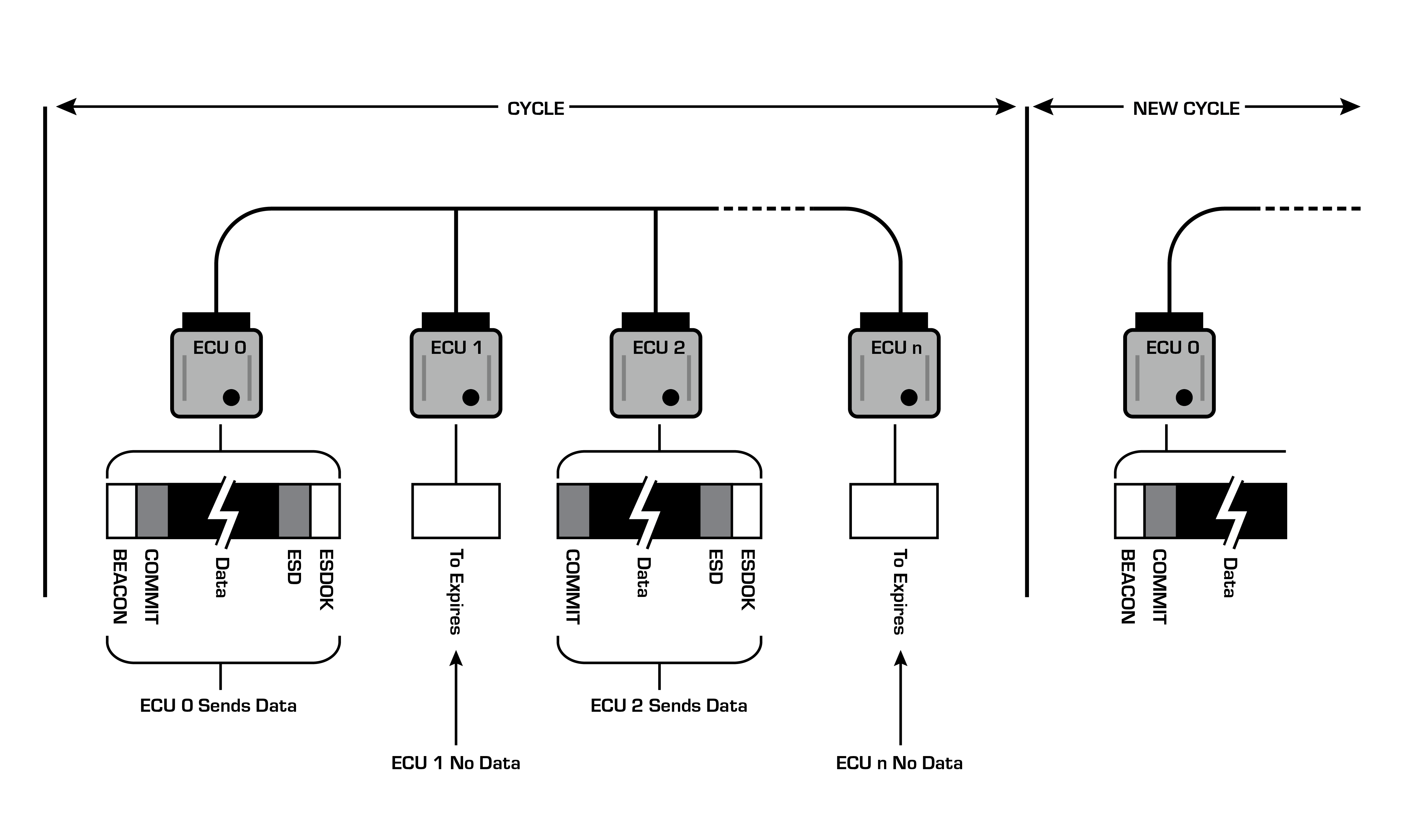
In PLCA, each node is assigned an ID starting with 0 and incrementing to the number of nodes minus one. Special data symbols are assigned that enable the PHYs to coordinate their transmit and receive activities. The node with ID 0 is responsible for sending one of these special symbols called a BEACON. The BEACON indicates the start of a network cycle where every node will have a transmit opportunity (TO) starting with node 0 until the node with the highest ID in a round-robin fashion. If a node has data to transmit, it will send a COMMIT during its TO to indicate to all other nodes that it will transmit data. After the COMMIT, the transmitting node will send data up to the maximum frame size and then two other special symbols: end of stream delimiter (ESD) and end of stream delimiter ok (ESDOK) if there was no error. If a node has no data to transmit, it will do nothing. After a number of configurable bit times, the default value is 32, the TO will expire, and the next node will be given its TO. After each node has had its TO, the cycle starts over with a new BEACON from node 0.
Overview of 10BASE-T1S multi-drop PLCA.
It is important to understand that the PLCA cycle can shrink and grow in time based on how many nodes transmit in each cycle and also how much data is transmitted per node. If no nodes transmit, this is the minimum possible cycle:

Minimum PLCA cycle, node0 to node3 don’t have data to transmit.
The maximum PLCA cycle happens if all nodes have the maximum amount of data to transmit.

Maximum PLCA cycle Symbols ESD and ESDOK at the end of the data bytes not shown.
PLCA Burst Mode:
An optional Burst Mode in 10BASE-T1S enables a node to transmit from 0 up to 255 additional packets during its Transmit Opportunity (TO). Burst Mode provides additional network flexibility for some use cases:
Asymmetric Data Transmission: It is common on an automotive network that one or a small number of ECUs produce much more data to be transmitted than other nodes, and this means that they have the need to transmit much more data than other nodes. This means that they have the need to transmit much more data than other nodes. With Burst Mode, more network bandwidth can be allocated to these heavy data producers by allowing them to transmit up to 255 additional packets of data per cycle.
Isochronous Data with a Cycle Time Less than the PLCA Cycle Time: Imagine a node that has the purpose of processing sound data, say from a microphone, and transmitting that sound data on the network. Let’s further say that a sound packet is produced at a 48kHz rate. That would mean one every 20us. If the PLCA cycle time is larger than that and the ECU was only allowed to transmit one packet per cycle, then there would be a backup of packets until an inevitable overflow of a buffer in the ECU. The ECU could potentially be programmed to buffer multiple audio data samples in one Ethernet packet for transmission; however, this could introduce unnecessary complexity in both the transmitter and receiver software. With the use of Burst Mode, the transmitter can simply transmit more than one packet of data per cycle.
If Burst Mode is enabled, the Transmit Opportunity starts as normal with a COMMIT at the start of the cycle, then a data packet. If the transmitting node intends to send an additional packet of data, then it will terminate the packet with ESDBRS and followed by ESDOK to indicate more data is coming. Next is a new COMMIT followed by another packet of data. This continues until the transmitting node finalizes its last packet of data. If the last packet of data is less than the maximum allowed based on the network configuration (e.g. variable “max_bc” in the specification), then it will simply send an ESD/ESDOK right after the COMMIT to complete the burst. If the last packet of data is the maximum allowable, then after this packet of data, an ESD followed by an ESDOK completes the burst.
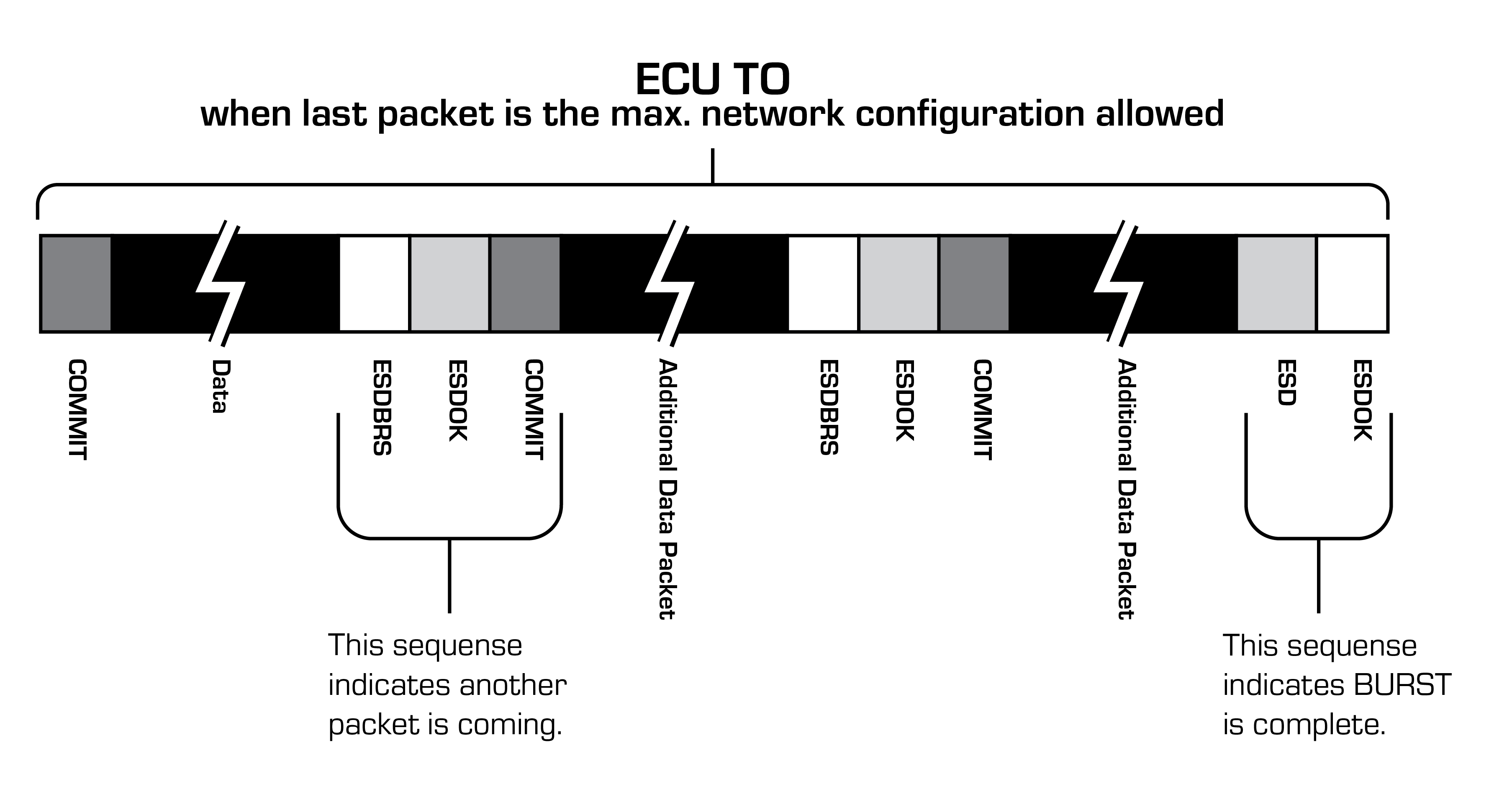
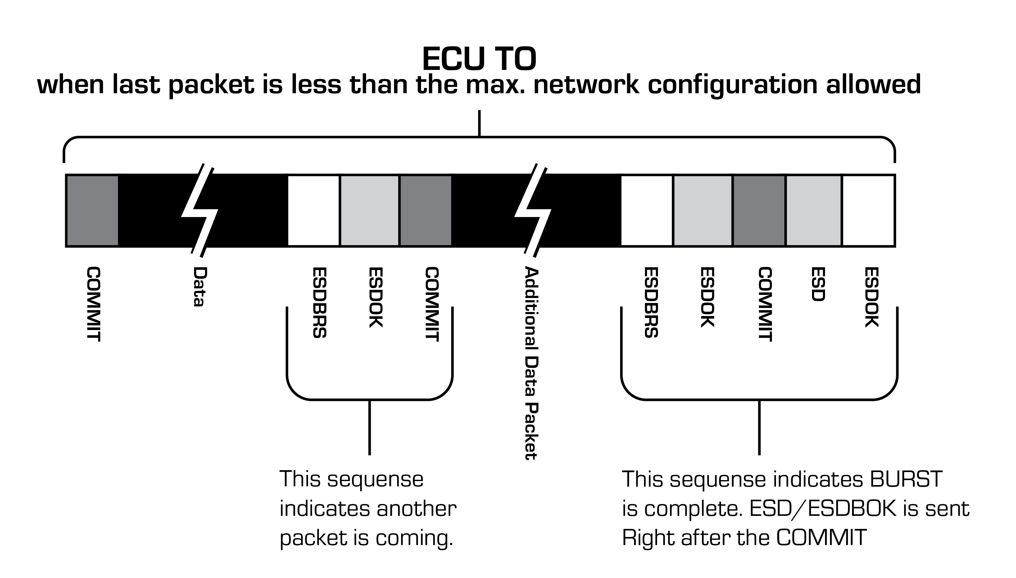
An ECUs Transmit Opportunity (TO) that shows Burst Mode Communication Sequence.
Intrepid’s 10BASE-T1S Hardware
RAD-Moon-T1S - 10BASE-T1S Media Converter
The Intrepid RAD-Moon family of Media Converters has a new member supporting the latest Automotive Ethernet technology. 10BASE-T1S is a low-cost, low-speed, multidrop version of Automotive Ethernet widely considered for the replacement of CAN and CAN FD.
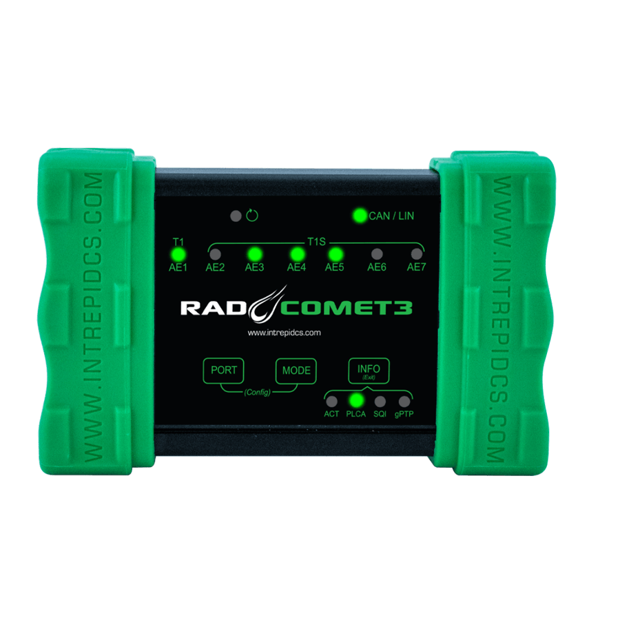
RAD-Comet 3 - 10BASE-T1S Converter
The RAD-Comet 3 is a versatile device for developing and testing 10BASE-T1S communication in automotive systems. It can be programmed to simulate a node on a 10BASE-T1S network as well as capture and analyze 10BASE-T1S traffic simultaneously with other vehicle networks.
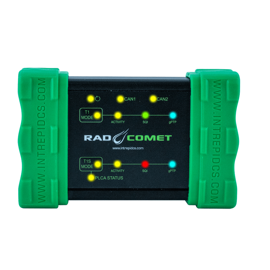
RAD-Comet 2 - 10BASE-T1S Converter
The RAD-Comet 2 is a versatile device for developing and testing 10BASE-T1S communication in automotive systems. It can be configured and used to simulate a node on a 10BASE-T1S network as well as capture and analyze 10BASE-T1S traffic simultaneously with other vehicle networks.

